AT89LP2052
/ AT89LP4052 Parallel Port Programmer
Programming the AT89 LP2052/LP4052 Flash Memory, Lock Bits
and User Fuses
The AT 89LP2052 / 89LP4052 microcontroller provide two interfaces
with same command format for device programming. The serial ISP
Programming interface of the new 2052/4052 microcontroller needs one
additional SS Signal for device programming. This SPI signal will be added
in the near future to the existing AT89ISP cable and Software (driver) for IDE.
You can find more details in the Atmel specifications.
This 2052 / 4052 programmer design uses the parallel programming mode via
Parallel Port. Only parallel programming can re-enable the ISP Fuse. This
programmer is also usefull if you need to write the user fuses to disable
the XTAL Osc Bypass fuse - e.g. to test the LP2052 in
existing 2051 hardware designs.
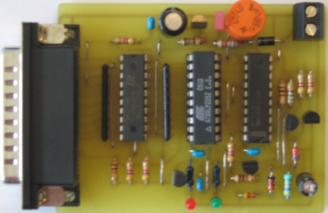
Programmer Hardware
The Dataport is connected via a 574 latch with 3 State outputs. The
strobe signal of the Parallel Port is used to latch the datas. The CS/ Signal
and Powersupply signals Vcc/Vpp of the micro are controlled through
the HC273 device. The Init signal of the parallel Port is used to
control these lines with the host software. The status of Vcc and Vpp
are displayed with two LEDs on the programmer board. An external
Oscillator is not required. The Atmel microcontroller is pulsed with the
Select_In signal from the parallel port.
An external power supply (16V= ) is needed to generate the 12V programming
voltage.
Visit www.atmel.com
to find an application note how to use the Parallel Port for existing
Atmel AT89 C/LV 51/52 devices.

Data polling is currently not supported to reduce the number of components
on the board. To verify the datas we still have to test the SPI
interface via parallel Port.
To minimize the influence of undefined
states it is necessary to start the host software (to disable Vcc and Vpp
!) before a 2052 / 4052 LP device is put into the socket.
Programmer Software
The programmer is controlled by software running on the host. The
software supports writing the flash memory (bin and hex files), Lock bits
and user fuses in parallel programming mode. The software can handle the
Vcc and Vpp signals of the microcontroller. The status of the signals
are displayed by LED 1 and LED 2 on the board.
The programming algorithm is
easy. You can can find detailed descriptions in the Atmel specs.
Some VB software parts (not complete):
Private Sub device_program_enable()
'Program enable sequence
DataWrite_Enable (True) ' enable 574 on Board
P32_CS_Signal (False) ' P3.2 CS to low
datasend
(&HAA)
' send preamble
datasend
(&HAC)
' send opcode
datasend
(&H53)
' send AdressHigh to enable
P32_CS_Signal (True) ' P3.2 CS to high
DataWrite_Enable (False) ' tristate 574 on Board
End Sub
Private Sub datasend(data As Byte)
'
send datas to micro, clocks 574 and clocks P_SelectIn
Out PortAddress, data ' send preamble
cr_strobe (cr_DataStrobe) ' P strobe for latch to 572
cr_strobe (cr_clkstrobe) ' SelectIn: strobe for
2052/4052 XTAL1
End Sub
Public Sub P32_CS_Signal(stat As Boolean)
' true means that signal on Board is high (= VCC =deactivated)
HC_Reg = HC_Reg Xor 2 ^ P32_CS ' toggle CS signal
Out PortAddress,
HC_Reg
' Daten anlegen
cr_strobe
(cr_InitStrobe)
' init strobe for 74HC273 Bit 0
End Sub
Questions ? Schaltplan und Layout im Eagle Format ?
Any input is welcome: Mail j.hulzebosch@gms2000.de