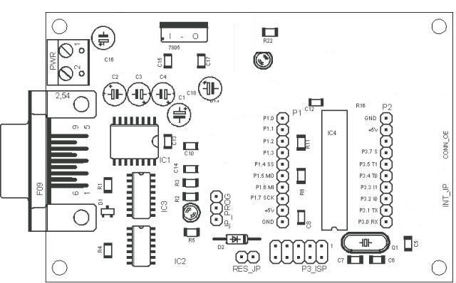
| - | serial Port with Maxim 232 for serial communication |
| - | 2 Pinheads for Port 1 and Port 3, Reset connector |
| - | ISP programmable via serial port with SS Signal support |
| - | 7805 / 78L05 regulator |
| - | Atmel compatible AT89ISP Pinheader or use integrated Serial-ISP interface for programming |
| - | This Board can be used for Flash programming with GMS Flash Software via RS232 |
| - | Easy IDE: upload your program via ser. Port (no additional Programmer needed) and start the device |
| Complete use of the SPI Port is possible because the
integrated Serial-SPI inteface can be disabled (tri stated) via
serial Port. Only one Jumper might be set to disable the On Board Serial-ISP
interface if the microcontroller program needs to communicate
via Serial Port after programming when the host Software
is using the RTS signal.
| |
| - | Optional (parts not mounted) DA converter with MAX538X, I2C programmable IRF FET Driver / parts for PWM with Elliptecmotor connector for optical encoders, INT 0 or INT1 interrupt support |
With this board you can test the Atmel LP microcontoller and learn more about
the LP2052/4052 PWM functions SPI or I2C Programming. The In Sytem
Programming allows you to download your programming code via Serial port
and to restart the microcontroller.
If you need the additional functions (e.g. Maxim DA converter, ISP
Programming, FET driver, optical encoder) then add the devices for your
requirement or expand this basic pcb with your own hardware
mounted on the pinheads.
As Atmel states on their hompage: Your designs will give your more than you
expected...
You can find more details about the microcontroller in the Atmel
specifications: (


|
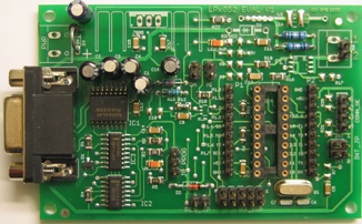
A picture of final version with reduced parts for
5V regulator (78L05), serial communication (Max232), ISP Pinhead for
programming and 11.052Mhz Crystal. |
Programmer Software
Programming the Flash through serial Port
is controlled by GMS software running on the host. The software supports
writing the flash memory (hex files), Lock bits and user fuses in SPI
/ISP programming mode. The software can handle the RST and
SPI signals of the microcontroller. The user must set one jumper
to program the non volatile Flash code memory of the device. Programming mode
ist displayed with one additional LED.
You'll find severals software examples for this design in the near future.
This PCB also supports Atmel compatible ISP header. That means that you
can use the Atmel ISP Programming Software ATMELISP.
Questions ?
Any input is welcome: Mail
j.hulzebosch@gms2000.de